I recently played around with various setups for my new home lab. One setup is fairly simple and old-fashioned, yet I like its flexibility: a virtualization environment using bridge mode.
This post is a write up using KVM and libvirt for such an installation.
Setup
The hypervisor machine is a single host, directly connected to a untrusted network (like the Internet). Consequently, network security must be taken into consideration. Simply bridging all virtual machines (VMs) to the Internet might not be a wise move.
The setup must allow all VMs controlled access to the Internet and vice versa (in case services are provided by the VMs).
The rationale of the setup laid out in this post is a virtual, hypervisor-internal network to which all VMs are connected. This network is isolated from any other network being internal or external to the hypervisor. Communication to the Internet is only possible through a firewall VM, which routes traffic between the untrusted network, connected to the hypervisor and the hypervisor-internal network.
The following diagram describes this setup:

In case only one public IP address is available, the firewall VM could be NAT-ed, instead of bridged and therefore would not require a separate public IP address.
Note that the firewall VM is directly exposed to the Internet through the bridge.
KVM installation
The example implementation in this post is based on Ubuntu 18.04.
Let’s start with a simple KVM setup:
- Check, if the hardware supports virtualization:
egrep -c '(vmx|svm)' /proc/cpuinfo. - Install required packages:
sudo apt install qemu qemu-kvm libvirt-bin bridge-utils - Make sure
libvirtdis running:systemctl status libvirtd.service
Network configuration
- Network configuration on Ubuntu 18.04 is done through an abstraction layer called
netplan. - Backup current network config.:
cp /etc/netplan/50-cloud-init.yaml /etc/netplan/50-cloud-init.yaml_back - The static IP address config. for the hypervisor might look something like this:
network:
ethernets:
    ens33:
        addresses: [172.16.6.10/24]
        gateway4: 172.16.6.2
        nameservers:
          addresses: [172.16.6.2]
        dhcp4: no
        optional: true
version: 2
Adding a bridge
The next step is to add the physical network adapter of the hypervisor to the bridge br0.
This moment is risky if performed on remote servers. If the configuration is faulty, connectivity might be lost and even netplan try will not be able to restore it (always perform this command in a terminal multiplexer like tmux or screen if logged in remotely to the hypervisor).
Also, note that adding a bridge, linked with the physical network adapter, means that the virtual interface (e.g. br0) is treated like a physical network adapter. It can be seen by the network connected to the hypervisor. Therefore, the bridge must be configured with a valid MAC address. In this scenario, the physical network adapter ens33 is added to the bridge, which means the bridge needs to have the same MAC address than the physical network adapter (at this point, please also think of NAC and other security controls in your network).
- Add the first bridge
br0to your config. (/etc/netplan/50-cloud-init.yaml):
network:
    ethernets:
        ens33:
            #addresses: []
            dhcp4: no
            dhcp6: no
    version: 2
    # renderer: networkd (depends on setup)

    bridges:
        br0: # network connection (firewall VM & physical network adapter)
            interfaces: [ens33]
            dhcp4: no
            addresses: [172.16.6.10/24]
            gateway4: 172.16.6.2
            nameservers:
                addresses: [172.16.6.2]
            # be aware: br0 MAC address is visible outside of the hypervisor. Generally, the network expects the MAC address of the physical network card.
            macaddress: 90:1b:0e:e0:d3:38

        br1: # hypervisor-internal network (firewall VM and VMs), 192.168.1.1 will be the IP address of the firewall VM
            interfaces: []
            dhcp4: no
            addresses: [192.168.1.2/24]
            #gateway4: 192.168.1.1 # will cause routing error, default gw is defined for br0
            nameservers:
                addresses: [192.168.1.1]
- The IP address is removed from the physical network adapter (
ens33) and is added to the bridge (br0). Simultaneously, the physical network adapter is added to the bridge. - The second bridge (
br1) can be ignored for now. - Test the netplan config.:
$ sudo netplan --debug try- if it works, apply config:
$ sudo netplan --debug apply
- if it works, apply config:
Verify network setup
- The network config. should then look similar to:
# ip a s
...
2: ens33: <BROADCAST,MULTICAST,UP,LOWER_UP> mtu 1500 qdisc fq_codel master br0 state UP group default qlen 1000
    link/ether 00:0c:29:03:34:98 brd ff:ff:ff:ff:ff:ff
<snip>
4: br0: <BROADCAST,MULTICAST,UP,LOWER_UP> mtu 1500 qdisc noqueue state UP group default qlen 1000
    link/ether 90:1b:0e:e0:d3:38 brd ff:ff:ff:ff:ff:ff
    inet 172.16.6.10/24 brd 172.16.6.255 scope global br0
       valid_lft forever preferred_lft forever
    inet6 fe80::14ad:85ff:fe60:7eef/64 scope link
       valid_lft forever preferred_lft forever
- Before continuing, ensure that the hypervisor has connectivity.
- At this point, the hypervisor-internal network can be added (
br1) as documented above to/etc/netplan/50-cloud-init.yaml. - After applying the netplan change, the network config. for
br1should look similar to:
 3: br1: <BROADCAST,MULTICAST,UP,LOWER_UP> mtu 1500 qdisc noqueue state UP group default qlen 1000
    link/ether b6:6c:25:b2:ee:ef brd ff:ff:ff:ff:ff:ff
    inet 192.168.1.2/24 brd 192.168.1.255 scope global br1
       valid_lft forever preferred_lft forever
    inet6 fe80::b46c:25ff:feb2:eeef/64 scope link
       valid_lft forever preferred_lft forever
- For the internal network, the IP address range
192.168.1.0/24has been selected. Pfsense is the firewall VM guest OS, which suggests this IP address range as the default LAN network and assigns itself192.168.1.1. The bridgebr1is configured with IP address192.168.1.2.
Installation of firewall VM
In order to have a working setup, the firewall VM needs to be set up first, connecting the hypervisor-internal network (br1) with the outer world through br0.
The VM can be created through virt-manager:
- Create VM
- Add a network adapter and configure it to connect to
br0: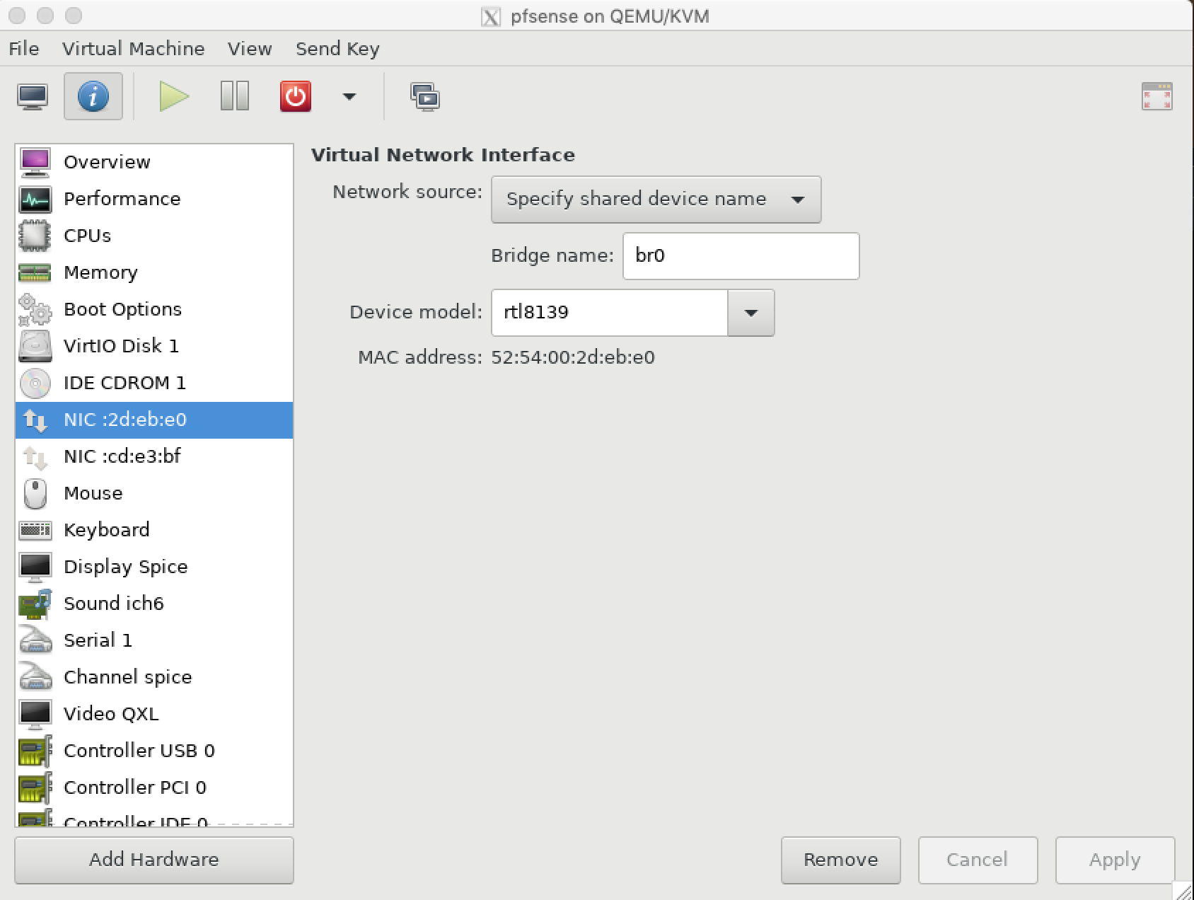
- Add a second network adapter and configure it to connect to
br1: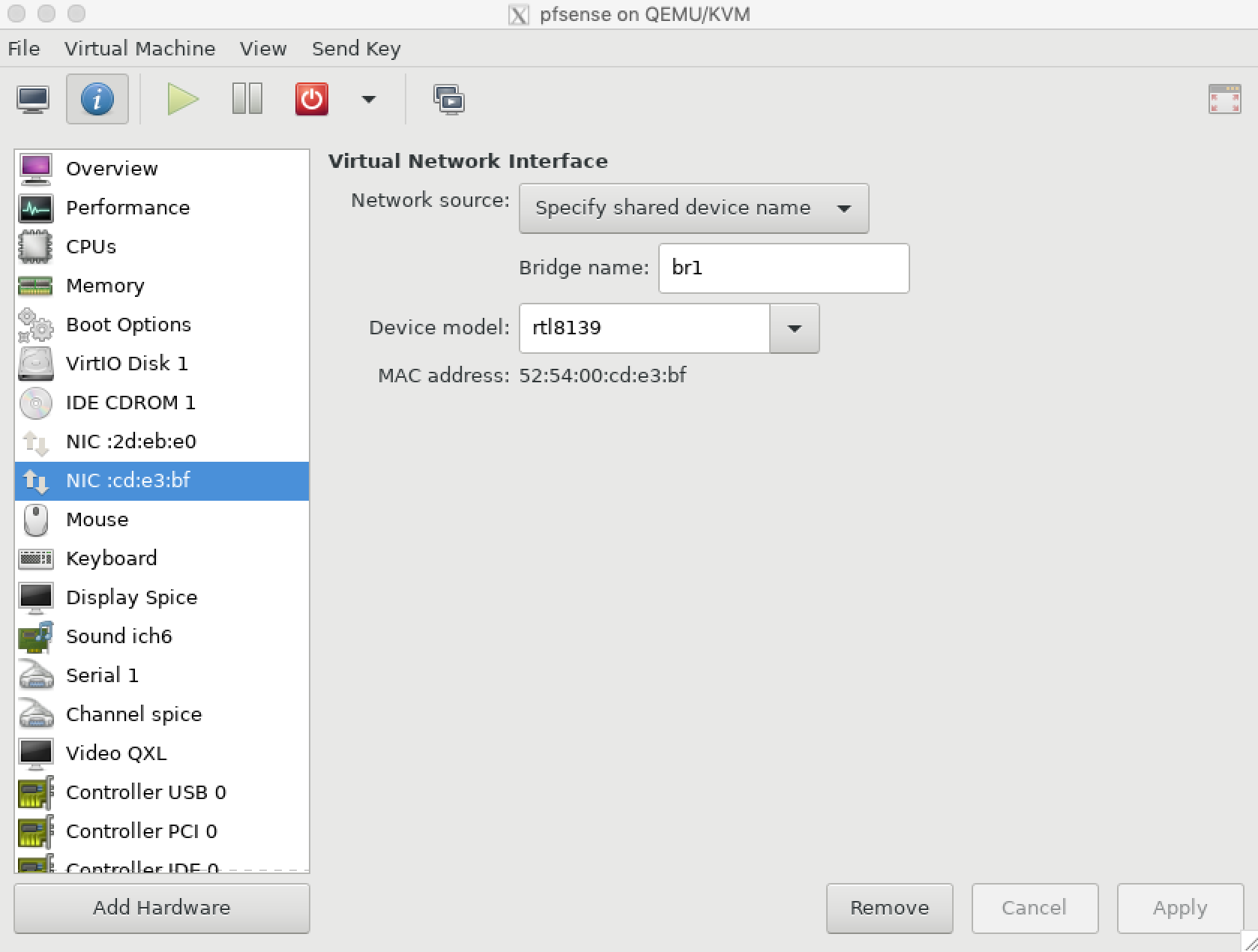
- Then install the firewall VM and configure it to use
br0as WAN interface andbr1as LAN interface: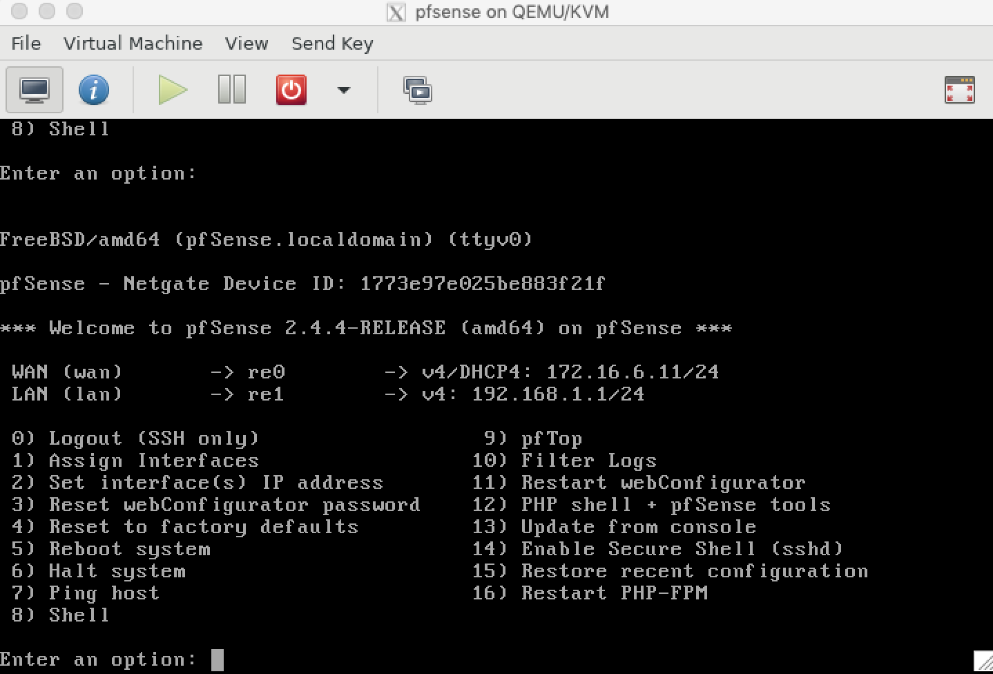
- Before continuing, make sure that the firewall VM has connectivity.
- As like most firewalls, the pfsense web UI is only accessible from the LAN. In order to connect to the web UI, use SSH port forwarding:
ssh -L localport:firewallVM-ip:firewallVM-port hypervisor-ip(example IP address configuration of this scenario:ssh -L 8888:192.168.1.1:443 172.16.6.10). - Use a browser to connect to
https://127.0.0.1:8888and start configuring your firewall.- Ensure that the firewall provides DHCP service on the LAN network adapter.
- Please note: Many firewall products, including pfsense expect (rightfully) that the WAN network is the public Internet, in which case private IP address ranges are blocked. If this is not true in your setup, allow private IP address ranges on the WAN network adapter (Pfsense > Interfaces > WAN > uncheck “Block private networks and loopback addresses”).
- At this point, the foundation has been set up and as many VMs as wished can be created and configured to connect to bridge
br1. Take note of the MAC address of every VM created and add it to the DHCPd config. of your firewall for static DHCP IP address management. - Observant readers might have realized that the VMs are configured to attach to the respective bridge. However, a VM cannot access a bridge directly. A VM can be configured to use a virtual adapter. The virtual adapter used by a VM can then be added to a bridge (as illustrated in the above diagram component
bridge n' taps). This step is automated in the background by libvirt: for every adapter added to a VM, a tap device (virtual network adapter) is automatically created and then added to the respective bridge. In this setup, two bridges have been configured:
# brctl show
bridge name     bridge id               STP enabled     interfaces
br0             8000.16ad85607eef       no              ens33 # hypervisor physical network adapter
                                                        vnet0 # WAN tap of firewall VM
br1             8000.b66c25b2eeef       no              vnet1 # LAN tap of firewall VM
                                                        vnet2 # tap of arbitrary VM
- The physical network adapter (
ens33) and the virtual network adapter (vnet0) of the firewall are member of bridgebr0.vnet1is the LAN network adapter of the firewall VM.vnet2is the virtual network adapter of the first VM connected to the internal network (e.g. a webserver VM). Every new VM added via libvirt will also create a tap device (vnetX), which is then added tobr1.
That is all it takes to set up a KVM-based virtualization environment using libvirt. The documented setup also elegantly evades a commonly known “conflict” between host firewalls and libvirt (see this blog post) 😄 👍.